Showing posts with label cnc mill. Show all posts

Friday, January 10, 2020

mini CNC routers/mills


I got a late start today in the shop. I's still working on the necklace for the cameo project, but I stayed up until 3am the night before getting the CAM ready for it. I also wrote CAM for the match boxes so I'm excited to go into mini production run mode on those. Today I started the necklace milling and while that job was running, I started work on a mini CNC router that I'm building for when I teach workshops on CNC and need to travel. This CNC is built with 3D printed parts and basic hardware. It's a simple little machine that will be good for milling foam and plastic molds and parts. I did decide to put an aluminum plate bed on it. It should turn this thing into a little tank. As I was making it I was thinking that most of the printed parts could/should be built in metal. 

Anyway as I was making this one, I started scrounging for some parts and came across a bunch of linear motion parts that I had along with some aluminum extrusion. I decided to start making an even smaller but super heavy duty version of my larger CNC router table but completely out of metal and with NEMA 23 steppers. I already have a Gecko G540  box to run it and I even have some ball screws that I can incorporate. The last picture is a teaser photo of the spoil board for the heavy duty CNC. I decided to give it a grab handle for carrying vertically. Stay tuned for more pics of these machines as they come together.

Again, it feels really good to just be doing manual layout and building on the fly. I'll CNC mill the parts I need to, but for now this allows me to build while my CNC cuts other things.

Thursday, April 3, 2014

zero your cnc machine


I came across this web article a few days ago. This post by Beatty Robots is just too good not to re-post. I'm sure my CNC friends will find it very interesting and useful in zeroing their machines. Enjoy and make sure to go check out Beatty Robots.


 zeroing a cnc

We enjoy machining custom aluminum robot parts on our CNC Mill. One of the best things about a CNC is that it can cut precise parts by following the geometry of a CAD drawing. We measure the precision and repeatability of our CNC in thousandths of an inch (0.001). But one of the challenges of using a CNC is to to get the raw material setup properly and make sure the spindle starts at exactly the right position. The CNC can only hold a precise position from its starting point. For example, let’s say you want to cut a pocket that is .050″ deep. That’s easy to do, but you need to start the CNC at the exact surface of the raw material so that it knows how far down along the Z-axis to move the spindle. Or let’s say you need to drill a precise hole pattern in a square sheet of aluminum. That’s easy to do, but you need to start the CNC at the exact corner of the square or your pattern will be way off. Finding the exact starting point is called “zeroing” the CNC. There are whole books written on the subject and a whole sub-industry of gizmos for handling this challenging problem. It took us a while to figure out, but this is what we’ve found to be the best solution for us:

1. When it comes to zeroing out the X and Y position of the CNC at the beginning of a job, we have tried a number of approaches, including eye-balling (not very accurate), mechanical edge finders (don’t like these), and even a laser edge finder (not as accurate and cool as you’d think). For our solution, we installed a super-cool USB camera microscope from our friends at Adafruit onto the frame of our spindle. We mounted the camera using a small aluminum bracket that we designed in SolidWorks and machined on our CNC. We secure the camera bracket to the spindle frame using a 4-40 threaded hole that we tapped for that purpose. The microscope camera points downward toward the raw material. It displays a large, magnified image on the computer screen, including crosshairs. When we want to set the X and Y zero point, we turn on the camera and then move the spindle until the crosshairs line up exactly with the corner of the raw material (or whatever position we want to identify as the zero point). Because it’s a microscope, it’s very precise. We then press the Mach3 “REF ALL HOME” button, which we’ve re-purposed and re-programmed to set the X=0 and Y=0 based on the offset distance between the camera crosshairs and the spindle position. This allows us to quickly and easily zero out the X and Y axis to the exact point we need to.


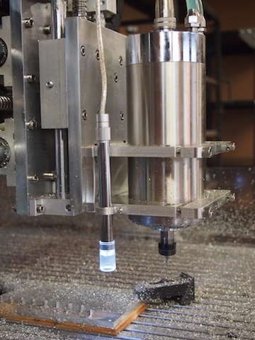
The microscope camera is the tall, tube-shape thing clamped to the edge of the spindle mount. It has a built-in ring of LED lights to illuminate the subject area.


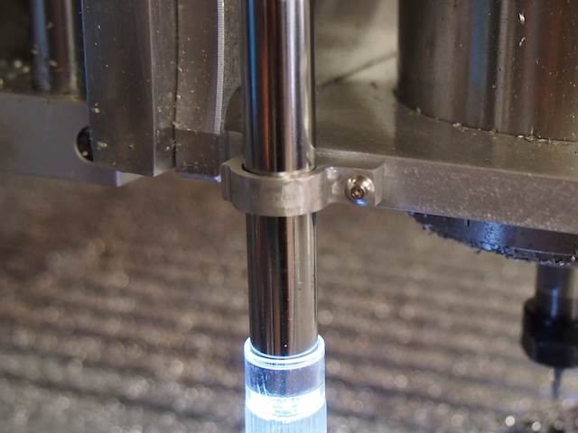
Close-up of the custom bracket we made to hold the tube-shpaed camera to the spindle frame


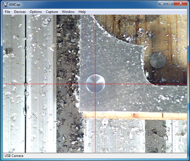
In this situation, we are using the crosshairs of the microscope to zero the CNC to the center of a tiny hole. The macro will set this as X=0, Y=0.


2. The Z-axis, which is the vertical position of the spindle, is by far the most important axis to zero out properly. For this, we rigged up a very cool solution that works great. We cut a piece of copper-clad circuit board (about 1″ x 1″) and soldered it to a long wire that we ran back to one of the 5 volt inputs on our controller. We ran another wire from the base of the CNC. These two wires, combined with the CNC and the end mill (which are both conductive), become like the leads of a voltmeter that is setup to test conductivity. We then wrote a macro in the BASIC language that runs when we press the “Auto Zero Tool” button on the Mach3 interface. When we want to zero-out the z-axis, we place the copper plate on the top of the raw material and press the button. The CNC moves the spindle slowly down toward the plate. The instant the tip of the end mill touches the copper plate the electrical circuit is closed. The macro instantly stops the spindle, sets the Z-axis zero point (by subtracting the .063″ thickness of the plate), and then moves up .125″ so that the copper plate can be removed. The whole process only takes a few seconds to complete. And the result is that the CNC determines exactly where the top surface of the material is and sets it as Z = 0.


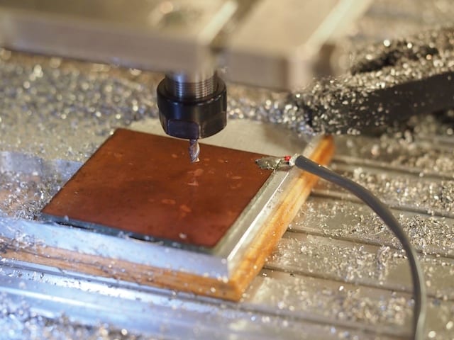
The zero plate is placed on top of the raw material. The macro automatically moves the spindle down until the end mill touches the plate and closes the electrical circuit, which signals the CNC to zero the z-axis. Note the wire soldered to the copper plate.

These two techniques have really helped improve our setup time and accuracy.


article by Beatty Robots


Sunday, December 8, 2013

joe's puzzle


Last Friday was a busy day. After meeting with Pascal at MIAD, having lunch with Chuck and in between having my SURF students in the studio working and working with Cherise and Nathaniel on the SCUBA scanner, I helped one of Adream's GD students cut a wood puzzle for his end of semester project. We cut it in some maple sheet that I had laying around the studio. Should be pretty cool after it's finished. Tonight I'm cleaning and organizing all of my computer files. I've made a folder just for placing this kind of project in and it seems I have a lot of work that I do like this for other people. The folder just keeps getting larger and larger.


Tuesday, November 26, 2013

tom's job


I did a milling job for Tom over the weekend. I had been meaning to get to this for a while, but just hadn't had the time to do so. I was feeling guilty with Eric up here and thinking about Tom's piece, so I threw a bit of time at it and banged it out. I probably would have made this a bit differently if I understand it's function correctly. After studying the design a bit more, I think I would have made this from thick walled aluminum square tube and then made an insert for the tip part so all I had to cut was the insert section with the mill (and then pin or plug weld the insert in place). That's the problem with just cutting the models that get sent to me.  I don't always have the opportunity to see the whole design. Reminds me of sitting on an assembly line and just seeing one parts of an objects assembly. Makes you miss out on the possibilities of what something could be. Just another reason to understand how to create something from start to finish and to have knowledge of several different processes. Anyway, now that I have the piece cut I can think of ways to make it more quickly if I were still cutting it on the mill if Tom so desires; such is life. Sorry for taking so long on this, Tom (let me know if I need to take this down from the blog too; wasn't sure if it was top secret or not)!


eric's prototypes


The Tormach got a work-out this weekend. I milled a bunch of pieces for Eric (sorry can't show these). I was primarily cutting aluminum but also did a little steel. This pic is of the coolant vibrating on the steel plate I was cutting. He came up and tweaked the prototype wheelchair parts that I milled and built up for him to test. He fine tuned things on Sunday night and Monday so he could have a properly functioning prototype while I continued to cut parts and assist in small jobs.


cnc'd wax pendant


This is the wax that Aaron milled for a pendant that he will he cast this past weekend. He was having trouble milling this on his Taig, so I told him to just mill it on my Tormach. He came in two weeks ago and set everything up while he was working his SURF hours for me in my studio. He even did a flip on this so he could mill the backside. He did an excellent job on indexing, the set-up of the CAM files, and the actual machining. I think he could have milled it quicker had he set some of this up as 2.5 axis operations, and doing his 3D work in a contained region, but he's still learning and I know he saw where he could have shaved some time off of the production of the piece. It was a good learning experience for him. I can tell he's getting confident with his abilities. So cool to see.


Wednesday, October 30, 2013

emily mondloch


Emily Mondloch (one of my students) came into get some help milling some new cabochons last week. She has started laminating wood and metal together and then milling different shaped cabochons from the block. We weren't sure how the layering was going to hold up to the milling, but these turned out great. I think she was as excited about using the Bridgeport as she was at using the Tormach. She has logged a lot of hours on the Tormach so I really feel like she's got her act together on setting a job up and running it without having any issues. She's still working on her RhinoCAM skills, but each job gives her more confidence and knowledge. Before long, she'll know more than I do. I took her and Aaron to Solaris last Friday to meet the CEO and to see about getting them internships in the Spring. It sounds like they're guaranteed paid internships if they want to pursue it. I hope this helps get them off on the right foot after graduation. I always worry about them after they leave...


Followers